Pronguino

Processing Pong with Arduino Controllers
Introduction
OK, so we have our basic Prong game — it’s time to transform it into Pronguino by adding Arduino paddle controllers. It’s going to be a simple circuit, but a great start to learn about voltage division, serial communications and bitwise operations.
Scope
| Description | |
|---|---|
| Circuit | Building a two-potentiometer controller circuit on the breadboard. |
| Arduino | Reading analogue values from the potentiometers, packing two 4-bit values into a single byte, and sending it to Processing over serial. |
| Processing | Receiving the serial data, unpacking the two nibbles, and using them to control the paddles. |
| Game | Replacing keyboard controls with the Arduino potentiometer controllers. |
Learning
| Description | |
|---|---|
| Potentiometers | How potentiometers work as voltage dividers and how the Arduino ADC converts the voltage to a 0–1023 value. |
| Serial Communication | How one-way serial communication works between the Arduino UNO and Processing. |
| Bitwise Operations | How to pack two 4-bit values into a single byte using bit shifting and bitwise OR, and unpack them with bit shifting and bitwise AND. |
| Fritzing | How to use Fritzing to produce breadboard layouts and schematics. |
| Tinkercad | How to simulate an Arduino circuit in Tinkercad before building it. |
Getting Started
First, we will focus on building the circuit and programming the Arduino UNO, making sure everything compiles and uploads OK.
Recommended
I recommend that you read and run through ‘Project 14 – Tweak the Logo’ in the Arduino Projects Book, as this will give a bit more background on what we are doing here.
Components
All the components you need are in the Arduino Starter Kit.
| Component | Quantity |
|---|---|
| Arduino UNO Rev 3 | 1 |
| USB Cable | 1 |
| Breadboard | 1 |
| Potentiometer 10kΩ | 2 |
| Jumper Wires | 6 |
| Black Stranded Jumper Wire | 1 |
| Red Stranded Jumper Wire | 1 |
The Circuit
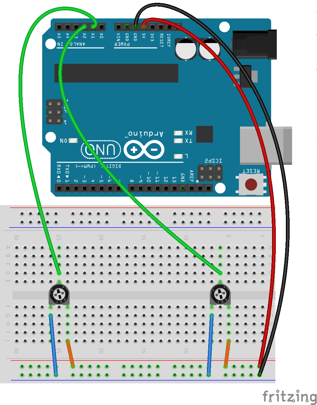
Assembly
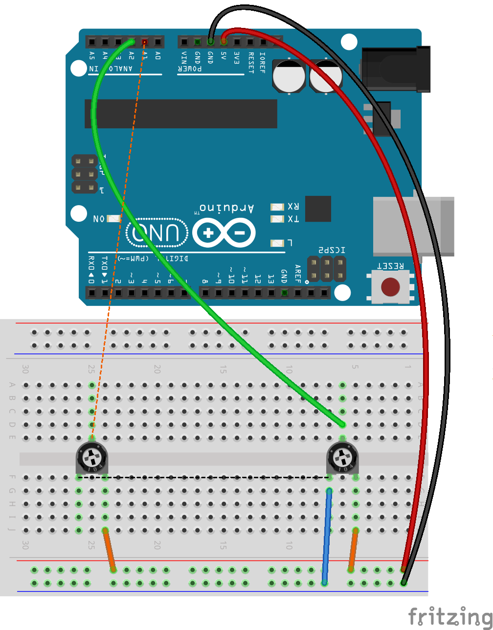
These instruction steps are used to assemble the circuit as shown above, quite straightforward with some added tips:
| Step | Instructions |
|---|---|
| 1 | Ensure you have unplugged from power source and at least one end of USB cable is removed from either the UNO / computer. |
| 2 | Connect the red stranded jumper wire to one of the bus lines on the breadboard marked with + to the 5V pin on the UNO. |
| 3 | Connect the black stranded jumper wire to the adjacent bus line marked with – to the GND (Ground) pin on the UNO. |
| 4 | The potentiometers that come with the kit have to straddle the centre of the breadboard, so place one on the left of the board so the side with two legs is facing the bus line where you connected the power. Place the other on the right-hand side. Make sure you press them in firmly, so they don’t wobble. |
| 5 | Connect one of the smaller jumper wires (15mm blue ones seem to do the trick) from a board socket aligned with the left leg of potentiometer to the – socket on the bus line where you have connected black wire. Do the same with the other potentiometer. |
| 6 | Connect another of the smaller wires (the 5mm orange one) from a board socket aligned with the right leg of potentiometer to the + socket on the bus line where you have connected red wire. Do the same with the other potentiometer. |
| 7 | On the other side of the board where the single legs (wipers) of the potentiometers are, connect a green jumper wire from a socket aligned with the wipers, to the Analog-In A1 pin on the UNO, for the left hand side potentiometer, and A2 for the one on the right. |
The Code
Arduino
We could write this code in a few lines in one file, but as I want to make the code more readable, understandable and extensible, I have broken it down into the following files …
| File | Description |
|---|---|
| pronguino | The main file. Similar to Processing, setup() initialises the serial communications and controllers, and loop() continuously reads the values from the controllers and writes them to the serial port. |
| Controller.h | Header file for the Controller library. |
| Controller.cpp | C++ implementation of the Controller library. Library Packaging will be covered in a later post. |
I will let the code speak for itself, and take a deeper dive into some areas below.
Plug the Arduino into your PC, upload the sketch, and we are ready for the next step.
Testing
Note: If you have a mobile phone or similar attached to your computer via USB, you may get some spurious results, bear this in mind if you are getting strange movement from paddles with or without Arduino attached.
So, we have the controllers built, code uploaded, and usually you would update the Processing code and spend the next few hours playing Pronguino, right? Or maybe the next few hours debugging two sets of code and an electronic circuit?
We haven’t got the luxury of a user interface on the UNO, but what we do have while connected to the PC is the Serial Monitor, which is opened from the Arduino IDE: Tools → Serial Monitor.
I have added a constant called TESTING, and when set to false, on upload of code, you should see something like this, as you turn the potentiometers, which is the data being written to the serial port.
⸮⸮⸮⸮⸮⸮⸮⸮⸮⸮⸮⸮⸮⸮⸮⸮⸮⸮⸮ѡ⸮⸮⸮⸮pppppP@A23#$$# @PP``acD4$#
If you change TESTING to be true, upload the new code, the setup() will call function resultsHeader() to print some headings, and loop() will continuously print the data being read from each controller via the function resultsDetail(), and the data that would be written, you should see something like below under various conditions ..
Both potentiometers turned to far left …
controllerValue1	controllerValue2	highNibble	lowNibble	data
0			0			0		0		0
0			0			0		0		0
0			0			0		0		0
Both potentiometers turned to far right …
controllerValue1	controllerValue2	highNibble	lowNibble	data
15			15			240		15		255
15			15			240		15		255
15			15			240		15		255
Both potentiometers turning to somewhere in the middle …
controllerValue1	controllerValue2	highNibble	lowNibble	data
11			10			176		10		186
8			10			128		10		138
8			8			128		8		136
Troubleshooting
Hopefully, with the circuit being quite simple, there is not much to go wrong, but the common things to check are as follows ..
| Issue | Solution |
|---|---|
| Nothing is working | Check Arduino is plugged in securely. Check red & black wires on board are secure |
| Random data (without change potentiometer) | Check potentiometers are firmly pushed in. Check the data wires are securely connected |
| Getting 15 instead of 0 as a nibble value, when potentiometer turned all way to left | Check the left pin of potentiometer is connected to GND, and right to 5V |
Program Storage Space
Just a quick note to those worried about testing code taking up valuable space on the Arduino, the compiler will not include any unreachable code, so when TESTING = false;, the functions resultsHeader() and resultsDetail(...) are not compiled, check console after compiling …
Sketch uses 1952 bytes (6%) of program storage space. Maximum is 32256 bytes. Global variables use 188 bytes (9%) of dynamic memory, leaving 1860 bytes for local variables. Maximum is 2048 bytes.
… in comparison to having TESTING = true; …
Sketch uses 2424 bytes (7%) of program storage space. Maximum is 32256 bytes. Global variables use 260 bytes (12%) of dynamic memory, leaving 1788 bytes for local variables. Maximum is 2048 bytes.
Processing
What’s New
| File | Description |
|---|---|
| Controller | Contains a new class Controller, which encapsulates the values received from Arduino controllers |
| Functions | A new static class Functions, which contains functions that can be called from anywhere in the package, initially used for some bitwise calculations |
What’s Changed:
| File | Changes |
|---|---|
| pronguino | Imports serial library. Initialises serial port in setup(). Added serialEvent() |
| Constants | Added controller related constants |
| Options | Added serial port related options |
| Player | Added Controller instantiation to constructor. Added setController(int value) method. Added checkController() method |
Experiment: The paddle movement seems OK when you are just turning the potentiometers at a steady rate, but can sometimes get out of sync. Have a tinker with checkController() in Player class and/or the timing of the outgoing data in Arduino code or incoming data in the Processing code to see if it can be improved.
Play
Take a break, and play one long (we will look into that soon) game of Pronguino.
Challenge: Currently, when turning controller to left the paddle moves up, and turning right moves it down. If you prefer the opposite, without changing the circuit, just edit either the Processing or Arduino code.
Potentiometers
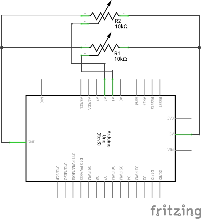
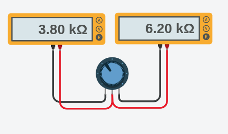
In the context of this circuit the potentiometers are being used as voltage dividers.
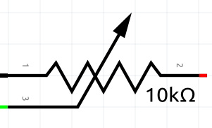
Terminal 1 (\(T_1\)) connected to GND
Terminal 2 (\(T_2\)) connected to 5V
Terminal 3 (\(T_3\)) connected to A1 or A2
Given that …
| Symbol | Description | From | To | Equation | Value |
|---|---|---|---|---|---|
| \(V\) | Voltage Supply | \(T_1\) | \(T_2\) | 5 Volts | |
| \(R\) | Total Resistance | \(T_1\) | \(T_2\) | \(R_1 + R_2\) | 10k Ohms |
… and turning the potentiometer to various positions, we would get the voltage drop required…
| Symbol | Description | From | To | Equation | Left | Middle | Right |
|---|---|---|---|---|---|---|---|
| \(R_1\) | Resistance | \(T_2\) | \(T_3\) | 10kΩ | 5kΩ | 0Ω | |
| \(R_2\) | Resistance | \(T_1\) | \(T_3\) | 0Ω | 5kΩ | 10kΩ | |
| \(V_{out}\) | Voltage | \(T_1\) | \(T_3\) | \(\frac{R_2}{R_1+R_2} \cdot V\) | 0V | 2.5V | 5V |
… which is then measured by analog inputs A1 or A2 and converted by the ADC (Analog-to-Digital Converter) into a resolution of 10 bits (0-1023).
Learn: I find it important to get to know your components, and how they work. It helps when things don’t work as planned. Learn some of the equations such as Ohm’s Law and Voltage Division Rule etc.
Bitwise Operations
Reference
| Operator | Name | Condition | Example | Result |
|---|---|---|---|---|
| & | AND | If both are 1 | 1 & 1 1 & 0 |
1 0 |
| | | OR | If either is 1 | 1 | 0 0 | 0 |
1 0 |
| ^ | XOR | If both different | 1 ^ 0 1 ^ 1 |
1 0 |
| ~ | NOT | Changes to opposite | NOT 0 NOT 1 |
1 0 |
| << | Left Shift | Shifts n bits left | 00001000 << 2 | 00100000 |
| >> | Right Shift | Shifts n bits right | 01000000 >> 3 | 00001000 |
| Term | Bits | Range (Binary) | Range (Hex) | Range (Decimal) |
|---|---|---|---|---|
| Bit | 1 bit | 0 to 1 | 0x0 to 0x1 | 0 to 1 |
| Nibble | 4 bits | 0000 to 1111 | 0x0 to 0xF | 0 to 15 |
| Byte | 8 bits | 00000000 to 11111111 | 0x00 to 0xFF | 0 to 255 |
| 0 | 1 | 2 | 3 | 4 | 5 | 6 | 7 | 8 | 9 | A | B | C | D | E | F |
|---|---|---|---|---|---|---|---|---|---|---|---|---|---|---|---|
| 0 | 1 | 2 | 3 | 4 | 5 | 6 | 7 | 8 | 9 | 10 | 11 | 12 | 13 | 14 | 15 |
| High | Low | ||||||
|---|---|---|---|---|---|---|---|
| bit8 | bit7 | bit6 | bit5 | bit4 | bit3 | bit2 | bit1 |
| bit8 | bit7 | bit6 | bit5 | bit4 | bit3 | bit2 | bit1 |
|---|---|---|---|---|---|---|---|
| 128 | 64 | 32 | 16 | 8 | 4 | 2 | 1 |
Arduino
In the Arduino code we have the following lines in the pronguino loop():
// Convert to nibbles
byte highNibble = (byte) controllerValue1 << 4;
byte lowNibble  = (byte) controllerValue2;

// Combine the two nibbles to make a byte
byte data = highNibble | lowNibble;
… where we have read the two values (ranging from 0 – 15) from each controller, and rather than sending these values individually, we will combine them into one byte to send…
Given that …
| Binary | Hexadecimal | Decimal | |
|---|---|---|---|
| controllerValue1 | 00001000 | 0x08 | 8 |
| controllerValue2 | 00001010 | 0x0A | 10 |
… to get the highNibble we shift controllerValue1 left 4 bits …
| Binary | Hexadecimal | Decimal | |
|---|---|---|---|
| controllerValue1 | 00001000 | 0x08 | 8 |
| << 4 | |||
| highNibble | 10000000 | 0x80 | 128 |
… we are only changing data type of controllerValue2 to get lowNibble, so to get data we bitwise OR highNibble and lowNibble …
| Binary | Hexadecimal | Decimal | |
|---|---|---|---|
| highNibble | 10000000 | 0x80 | 128 |
| | lowNibble | 00001010 | 0x0A | 10 |
| data | 10001010 | 0x8A | 138 |
Processing
In the Processing code we have two functions in the Functions file:
/**
 * Extracts a high nibble (first four bits) from a byte
 *
 * @param  data  byte to extract nibble from
 */
static int getHighNibble(byte data) {
  return (int) ((data >> 4) & (byte) 0x0F);
}

/**
 * Extracts a low nibble (last four bits) from a byte
 *
 * @param  data  byte to extract nibble from
 */
static int getLowNibble(byte data) {
  return (int) (data & 0x0F);
}
When the serialEvent() function receives the data sent from the Arduino, it needs to be split up to identify the movement of each of the controllers … for controller 1, getHighNibble(byte data) is called …
First the data needs shifting to the right 4 bits …
| Binary | Hexadecimal | Decimal | |
|---|---|---|---|
| data | 10001010 | 0x8A | 138 |
| >> 4 | |||
| result | 00001000 | 0x08 | 8 |
… and then apply a bitwise AND with 0x0F …
| Binary | Hexadecimal | Decimal | |
|---|---|---|---|
| result | 00001000 | 0x08 | 8 |
| & 0x0F | 00001111 | ||
| highNibble | 00001000 | 0x08 | 8 |
.. and to get value for controller 2 we call getLowNibble(byte data) .. and bitwise AND data with 0x0F ..
| Binary | Hexadecimal | Decimal | |
|---|---|---|---|
| data | 10001010 | 0x8A | 138 |
| & 0x0F | 00001111 | ||
| lowNibble | 00001010 | 0x0A | 10 |
Fritzing
Fritzing provides a software tool that allows you to draw schematics, mock up your breadboard, upload code to devices, design PCB layouts and also offers a service to print PCBs. I have used this to produce the schematic and breadboard mock-up for the “controllers”.
Learn: It is definitely worth getting to grips with circuit design and prototyping with tools such as Fritzing, even for the simplest of circuits, as when they become more complex, you want to be focusing on the circuit and not how to use the tool!
The cool thing about doing this using Fritzing, is the schematic and breadboard are continuously checking and modifying each other. For example, if you started with the breadboard and just add the required components on, without any wires, then go to schematic and connect everything up logically, switching back to the breadboard will show dashed lines from pins to sockets as a guide to where the wires should go (known as a ratsnest), and will disappear as wires are added.
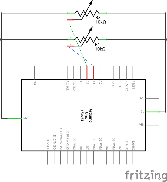
Note, as the ratsnest is being created from a logic diagram, they will take the most direct route i.e. joining pins from one potentiometer to the other as they are both connected to GND, and as we don’t want all the wires going from component to component, in this case we would take a wire from each component to a GND socket on the board.
Similarly, if you started with a fully wired up breadboard, and then switched to create schematic, you have to re-arrange the connections and components to create a tidy looking diagram, the connections will highlight red where no connection has been made, and green when all good, ratsnest guides are also created in this view.
This Fritzing file is included in the download for this post.
Tinkercad
Flipped your LED? Fried your chips? Or toasted your breadboard? If you haven’t yet and you’re paranoid about forgetting to put that resistor in, then it is worth taking a look at Tinkercad. Whilst Fritzing suits my needs for schematics and breadboards, I searched around for some free simulation software, and for basic Arduino circuits, this fitted the bill.
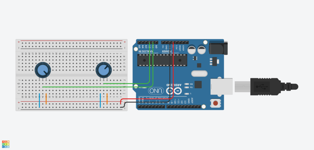
It has all the components from Arduino Starter Kit, and more. As you get more daring with your circuits, you may want to try it out first with Tinkercad — it will show you when something blows. Also useful for measuring resistance/voltage etc as you can add a multi-meter.

Tinkercad Limitations:
| Limitation | Workaround |
|---|---|
| As it is web based you cannot communicate with a physical serial port | Set TESTING = true and use the virtual serial monitor |
| You cannot add files to code window (e.g., Controller.cpp and Controller.h) | Implement the class Controller at the top of the main file |
Code
/**
  Pronguino.ino - Main file for controllers

  Tinkercad version

  Parts required:
  - 2 x 10 kilohm potentiometers

  @author  Neil Deighan

*/

// Controller class
class Controller
{
  public:
    Controller() {}
    Controller(int pin) {
      _pin = pin;
    }

  	int read() {
      // Reads value from pin, which would be a value mapped from 0 to 5V (0 to 1023)
      int pinValue = analogRead(_pin);

      // Small delay to allow the Analog-to-Digital Converter (ADC) to process
      delay(1);

      // Map the pin value to number between 0 and 15
      int value = map(pinValue, 0, 1023, 0, 15);

      return value;
    }


  private:
    int _pin;
};

// Define constants
const int CONTROLLER_COUNT = 2;
const int CONTROLLER_ONE = 0;
const int CONTROLLER_TWO = 1;
const int CONTROLLER_ONE_ANALOG_PIN = A1;
const int CONTROLLER_TWO_ANALOG_PIN = A2;

// Special constant to turn on / off testing mode
const bool TESTING = true;

// Declare controllers
Controller controllers[CONTROLLER_COUNT];

/**
  Setup the serial communications and controllers
*/
void setup() {

  // Initialize serial communication
  Serial.begin(9600);

  // Create Controllers
  controllers[CONTROLLER_ONE] = Controller(CONTROLLER_ONE_ANALOG_PIN);
  controllers[CONTROLLER_TWO] = Controller(CONTROLLER_TWO_ANALOG_PIN);

  // Print debug headers
  if (TESTING) {
    resultsHeader();
  }

}

/**
  Continuously read/write controller values
*/
void loop() {

  // Read the values from each controller
  int controllerValue1 = controllers[CONTROLLER_ONE].read();
  int controllerValue2 = controllers[CONTROLLER_TWO].read();

  // Convert to nibbles
  byte highNibble = (byte) controllerValue1 << 4;
  byte lowNibble  = (byte) controllerValue2;

  // Combine the two nibbles to make a byte
  byte data = highNibble | lowNibble;

  if (TESTING) {
    // Print results detail
    resultsDetail(controllerValue1, controllerValue2, highNibble, lowNibble, data);
  } else {
    // Write the data to serial port
    Serial.write(data);
  }

  // Delay 150 milliseconds
  delay(150);
}

/**
   Print Results Header to Serial Monitor
*/
void resultsHeader() {
  Serial.print("controllerValue1\t");
  Serial.print("controllerValue2\t");
  Serial.print("highNibble\t");
  Serial.print("lowNibble\t");
  Serial.print("data\t");
  Serial.println();
}

/**
   Print Results Detail to Serial Monitor
*/
void resultsDetail(int controllerValue1, int controllerValue2, byte highNibble, byte lowNibble, byte data) {
  Serial.print(controllerValue1); Serial.print("\t\t\t");
  Serial.print(controllerValue2); Serial.print("\t\t\t");
  Serial.print(highNibble); Serial.print("\t\t");
  Serial.print(lowNibble); Serial.print("\t\t");
  Serial.println(data);

  // Slow it down a bit, so can be read, waits one second
  delay(1000);
}
This TinkerCad code is included in the download for this post.
Conclusion
We now have Pronguino up and running, with two potentiometer-based Arduino controllers communicating with Processing over serial. Along the way we covered voltage division and analogue-to-digital conversion, packed and unpacked controller values using bitwise operations, and used Fritzing and Tinkercad to design and simulate the circuit. Hopefully the level of detail here gives you a useful reference to look back on. Next up … updating the look with Praint to explore more of what Processing can do.