Servuino
Introduction
Time to add a few more components to the circuit, add some additional functionality and have a bit more of a tidy up in the code, adding game state and “event” driven in areas. Also introducing two-way communications between PC and Arduino UNO and building a code library.
Currently the game just starts automatically and the ball moving part-randomly at the beginning, so adding the ability for user to control the serve, pause and resume the game.
Scope
| Description | |
|---|---|
| Circuit | Adding two tactile switches and two LEDs to the existing circuit. |
| Arduino | Building a component library. Sending and receiving data over serial. |
| Processing | Building a project library. Sending and receiving data over serial. |
| Game | Adding game state, event-driven actions, player-controlled serve, pause and resume. |
Learning
| Description | |
|---|---|
| Pull-down Resistors | How pull-down resistors are used to guarantee a stable LOW signal on a digital input pin. |
| Fixed Resistors & LEDs | How to calculate the correct resistor value for an LED using Ohm’s Law and the LED datasheet. |
| Bitwise Operations | How to pack and unpack multiple values into a single byte for serial communication. |
| Serial Communication | How two-way communication works between the Arduino UNO and Processing over serial. |
| Code Libraries | How to structure reusable code into libraries in both Arduino and Processing. |
Getting Started
Recommended
I recommend reading through the Pronguino post, as we are building circuit on top of the result of this.
Components
All the components that you need listed here are in the Arduino Starter Kit, as mentioned above, this is being built on top of previously built circuit, see existing components list, as well as the following…
| Component | Quantity |
|---|---|
| Button (Tactile Switch) | 2 |
| Resistor 10k Ω | 2 |
| Yellow LED | 2 |
| Resistor 220 Ω | 2 |
| 10mm Green wire | 2 |
| 100mm Yellow wire | 2 |
| 75mm Orange wire | 2 |
| 50mm Red wire | 2 |
Note: I have been specific on the length in particular on the above wires, mainly for the smaller ones that are used just on the breadboard, so they are as flat as possible.
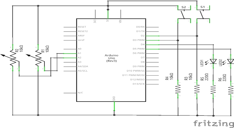
The Circuit
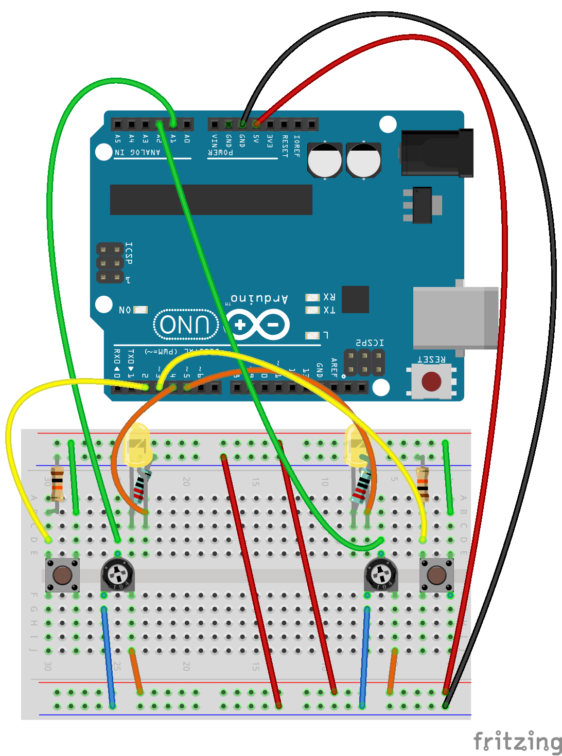
Fritzing Breadboard - Servuino
Assembly
These instruction steps are used to assemble the circuit as shown above, a little more tricky than previous, you need a steady hand.
| Step | Instructions |
|---|---|
| 1 | Ensure you have unplugged from power source and at least one end of USB cable is removed from either the UNO / computer. |
| 2 | Take each of the 50mm red wires and connect the two bus lines + to + and – to – respectively. |
| 3 | The switches that come with the kit (at time of publishing this), are best to straddle the centre of the breadboard, so place one on the left of the board next to the potentiometer. Only one orientation of the button should fit. Place the other on the right hand side. Make sure you press them in firmly, so they don’t wobble. |
| 4 | Take one of the 10k Ω resistors, place one pin into a board socket aligned with the top left pin of switch on left (leaving at least one socket between), and the other pin into a – socket on the top bus line. Repeat for the other 10k Ω resistor for right side switch. |
| 5 | Insert one end of a 100mm yellow wire into a board socket in between the switch and resistor placed in previous step, and the other end into digital pin D2. Repeat for the other 100mm yellow wire for right side switch, placing the other end of wire into digital pin D3. |
| 6 | Insert one end of a 10mm green wire into a board socket aligned with the top right pin of the switch on left, and the other end into a + socket on the top bus line. Repeat for the other 10mm green wire for right side switch. |
| 7 | Identify two clear strips of board sockets, just to the right of the left side potentiometer, and place one of the LEDs across these strips around the middle, I have put the long pin (anode) of the LED to the right in this case, just remember which. Repeat for the right side of board with other LED. |
| 8 | Take one of the 220 Ω resistors, and place one pin into a socket aligned with the left pin of LED (cathode), and the other into a – socket on the bus line. Repeat for other 220 Ω resistor on other side of board. |
| 9 | Insert one end of a 75mm orange wire into a board socket aligned with the right pin (anode) of the LED on left, and the other end into digital pin D4. Repeat for the other 75mm orange wire for right side LED, placing the other end of wire into digital pin D5. |
Note: It is recommended not to use digital pins 0 and 1, due to them being used by USB serial communication.
The Code
Arduino
What’s New
Component Library
As some new components have been introduced, I have added a low level library containing classes to encapsulate basic components called Component.
| File | Description |
|---|---|
| Component.ino | Dummy sketch for library. |
| Component.h | Header file for Component library. |
| Component.cpp | C++ implementation of Component.h – Potentiometer class – Switch class – LED class |
Pronguino Library
… also a new project specific library called Pronguino, that utilizes the Component library, for example, to convert raw data from components into usable data i.e. controller value.
| File | Description |
|---|---|
| Pronguino.ino | Dummy sketch for library |
| Pronguino.h | Header file for Pronguino library (replaces Controller.h) |
| Pronguino.cpp | C++ implementation of Pronguino.h (replaces Controller.cpp) – Controller class |
What’s Changed
Pronguino Sketch
Creating libraries has a number of benefits, such as, being able to re-use code, keep the main sketch a lot less cluttered, easier to read.
Within the code download, there is a folder called arduino/libraries, inside there are two folders called Component and Pronguino, copy these to the libraries folder in the location specified from IDE menu option … File -> Preferences -> Settings -> Sketchbook location ….
Now, you should only need to open the Pronguino sketch and compile, you may have to restart IDE. You won’t see these libraries in the Library Manager as they are just local. maybe in time I will publish a library, and talk you through that.
| File | Changes |
|---|---|
| pronguino.ino | Uses new Pronguino library. Refactored slightly. Only writes serial data on change of values |
Testing
As previously, if you change TESTING to be true, upload the new code, the setup() will call function resultsHeader() to print some headings, and will also read the initial values of the two controllers, and the state of the buttons, so if you turn both potentiometers to the left, clear the serial monitor, and press the reset button on UNO .. you should see the following result.
controllerValue1 buttonState1 highNibble controllerValue2 buttonState2 lowNibble data 1 0 16 1 0 1 17 1 0 16 1 0 1 17
The loop() function is now continuously reading from each controller and button, checking for a change in any of the values, when a change is detected, resultsDetail() will print the values, , note the bold values that change, so …
Turn left potentiometer to right a bit …
controllerValue1 buttonState1 highNibble controllerValue2 buttonState2 lowNibble data … 1 0 16 1 0 1 17 2 0 32 1 0 1 33 3 0 48 1 0 1 49
Press and release the left button …
controllerValue1 buttonState1 highNibble controllerValue2 buttonState2 lowNibble data
…
3 0 48 1 0 1 49
3 1 176 1 0 1 177
3 0 48 1 0 1 49
Turn right potentiometer to right a bit …
controllerValue1 buttonState1 highNibble controllerValue2 buttonState2 lowNibble data
…
3 0 48 1 0 1 49
3 0 48 2 0 2 50
3 0 48 3 0 3 51
Press and release the right button …
controllerValue1 buttonState1 highNibble controllerValue2 buttonState2 lowNibble data
…
3 0 48 3 0 3 51
3 0 48 3 1 11 59
3 0 48 3 0 3 51
Note: So the they can be tested and make sure wired up OK, the relevant LED will light up when pressing either of the buttons, this only happens when in test mode.
Troubleshooting
A little more fiddly this circuit, a few more components and wires to check ..
| Issue | Check |
|---|---|
| Nothing is working | Check Arduino is plugged in securely. Check red & black wires on board are secure. Check wires connecting bus lines. |
| Random data in Serial Monitor (without change potentiometer) | Check potentiometers are firmly pushed in. Check the data wires are securely connected. Check buttons are firmly pushed in along with data wires and resistors. |
| LED not emitting light (when button pressed in test mode, or when player waiting to serve) | Check LEDs and resistors firmly pushed in. Check the data wires are connected. |
Processing
In line with the Arduino code above, have add Button and Indicator classes to encapsulate the state, had quite a bit of a tidy up in the code, made adjustments for the lower range of values coming in from the controller, and removed the previous random start position / direction of ball, putting the player in control…
What’s New
| File | Description |
|---|---|
| Button | Contains a new class Button, which encapsulates the state received from the switches. |
| Indicator | Contains a new class Indicator, which encapsulates the setting of state of the LEDs. |
What’s Changed
| File | Changes |
|---|---|
| Ball | Removed random start direction. |
| Constants | Added more constants for state, button, indicator and data bit masks. |
| Controller | Added Button as a child. Added Indicator as a child. Added connected flag. Refactoring |
| Debug | Rename of a flag |
| Functions | Use of data bit mask constants. New function to create outgoing data |
| Paddle | Added speed factor. |
| Player | Removed “wrapper” methods for child objects. Refactoring |
| pronguino | Added game state (i.e. paused, ended etc ..). Added game actions (i.e. pause, resume etc ..). Added new event methods i.e. buttonPressed. Refactoring |
Challenge: As I was finishing the code for this stage of project, I saw a need for another class to help keep things tidy … Game … have a go at creating and implementing this class, maybe include state ? … and the actions ?
Play
Break time … Turn off testing mode, and re-upload …. when player misses the other player serves next, while the player has the ball the relevant LED should light, and will turn off when they serve, either using the keyboard or “controller”…
| Player | Up | Down | Pause/Resume/Serve |
|---|---|---|---|
| 1 | q |
a |
space |
| 2 | p |
l |
space |
Key Controls
Rules
As this project progresses, these will be reviewed and improved to get closer to the real rules of ping pong. The game rules that have been implemented so far, are as follows…
| Rule | Description |
|---|---|
| Game Over | The first player to SCORE_MAX wins the game. |
| Opening Serve | PLAYER_ONE has the first service. |
| Player Misses | The other player serves. |
| Serve Direction | If the player serving has paddle in top half of surface, the direction will be down/left or right depending on player. If the player serving has paddle in bottom half of surface, the direction will be up/left or right depending on player. |
Fixed Resistors
At a basic level, resistors are used in circuits to reduce current flow, in the context of this circuit, I will describe the use of the fixed resistors along with switches and LEDs below.
Switches
The switches used in this circuit are momentary switches, so they close the circuit when pressed, and open circuit when released, for example, S1 is connected as follows…
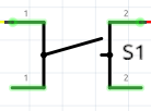
Terminal 1 ($T_1$) connected to digital pin D2 and also, through a 10k Ω pull-down resistor to GND.
Terminal 2 ($T_2$) connected to 5V
The digital pins, when mode is set to INPUT, will either read as HIGH (~5V), or LOW (~0V).
When the pins are not connected to anything there is a small input leakage current, looking at the datasheet on page 259, both the low/high max current is $1\,\mu A\,(0.001\,mA)$, and the input would float between HIGH and LOW.
In order to guarantee a small enough voltage, say $0.01V$ to register as LOW when the switch is unpressed, we need to connect the pin to GND through a resistor known as a pull-down.
Using Ohm’s Law, we would calculate the required resistance with the following equation…
… so, given the values from above…
.. would give a result of…
LEDs
An LED (Light-Emitting Diode) is a component that emits light when current flows through it, also electricity only flows in one direction, in this circuit we have, for example, LED1 wired as follows…
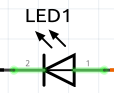
Terminal 1 ($T_1$) connected to digital pin D4
Terminal 2 ($T_2$) connected to GND through a $220Ω$ resistor.
Digital pin D4 has been configured as OUTPUT, when this pin is set to HIGH, the LED will light up.
So the LED doesn’t burn out too quickly, we need to put a resistor in series with LED, reduce the current, to calculate the Ohm value of this resistor, we would use the formula…
… where…
| Symbol | Description | Value |
|---|---|---|
| $V_s$ | Voltage Supply | \(5V\) |
| $V_f$ | Forward Voltage (LED) | \(2.1V\) * |
| $N$ | No. of LEDS | 1 |
| $I_f$ | Forward Current (LED) | \(0.02A\) (\(20mA\)) * |
* These values where take from the datasheet, using the typical forward voltage, and test conditions.
… so…
… resulting in…
… but, there is no single 145 Ω standard value resistor, the nearest value would be 150 Ω*, however, the smallest value resistor in the Starter Kit is 220 Ω, so as we are using this, the forward current will be calculated as..
* Based on similar resistors available at ±5% tolerance in datasheet
… giving…
.. which is more than enough to light it up, which is worth bearing in mind with LEDs, even though the datasheet states a maximum of \(30mA\), you don’t really need it that bright for most applications.
Learn: I find it important to get to know your components, and how they work, it helps when things don’t work as planned, look up the datasheets of the components to get data to be used to equations such as Ohms law to make sure you choose correctly.
Bitwise Operations
The serial port transmits one byte (8 bits) at a time. Previously, the full byte was used to carry just one controller value. Now that we also need to carry a button state alongside the controller value, and need to do this for two players, we need to be smarter about how we pack data into that single byte.
The solution is to split the byte into two nibbles (4 bits each) — one for each player — and within each nibble, use the lower 3 bits for the controller value (giving a range of 0–7) and the 4th (most significant) bit for the button state (0 or 1).
| 7 | 6 | 5 | 4 | 3 | 2 | 1 | 0 | |
|---|---|---|---|---|---|---|---|---|
| Nibble | highNibble — Player 1 | lowNibble — Player 2 | ||||||
| Field | button | value (0–7) | button | value (0–7) | ||||
| Example | 1 | 0 | 0 | 1 | 0 | 0 | 0 | 1 |
Example: Player 1 — value 1, button pressed (1). Player 2 — value 1, button not pressed (0). data = 10010001 = 0x91 = 145
Bitwise operators are used to pack this data on the Arduino side, and unpack it on the Processing side.
Arduino
This code is a snippet from the createData(...) function in the main pronguino.ino file, it receives the values read from the potentiometers and states from the switches, and creates the data to be written to the serial port…
// Convert to nibbles
byte highNibble = (byte) (controllerValue1 | buttonState1 << 3) << 4;
byte lowNibble  = (byte)  controllerValue2 | buttonState2 << 3;

// Combine the two nibbles to make a byte
byte data = highNibble | lowNibble;
.. so, using the example from the bit-map above — Player 1 controller at minimum (value 1), left button pressed (1), Player 2 controller at minimum (value 1), right button not pressed (0) — the function is given …
| Binary | Hexadecimal | Decimal | |
|---|---|---|---|
| controllerValue1 | 00000001 | 0x01 | 1 |
| controllerValue2 | 00000001 | 0x01 | 1 |
| buttonState1 | 00000001 | 0x01 | 1 |
| buttonState2 | 00000000 | 0x00 | 0 |
.. to calculate the highNibble, first we need to left shift the buttonState1 3 positions ..
| Binary | Hexadecimal | Decimal | |
|---|---|---|---|
| buttonState1 | 00000001 | 0x01 | 1 |
| << 3 | |||
| result | 00001000 | 0x08 | 8 |
.. and then bitwise OR result and controllerValue1 …
| Binary | Hexadecimal | Decimal | |
|---|---|---|---|
| result | 00001000 | 0x08 | 8 |
| | controllerValue1 | 00000001 | 0x01 | 1 |
| result | 00001001 | 0x09 | 9 |
.. then left shift four bits …
| Binary | Hexadecimal | Decimal | |
|---|---|---|---|
| result | 00001001 | 0x09 | 9 |
| << 4 | |||
| highNibble | 10010000 | 0x90 | 144 |
… in this example the controllerValue2 is 1, and button is not pressed, so, for simplicity lowNibble would be just 1, and to calculate data to send …
| Binary | Hexadecimal | Decimal | |
|---|---|---|---|
| lowNibble | 00000001 | 0x01 | 1 |
| | highNibble | 10010000 | 0x90 | 144 |
| data | 10010001 | 0x91 | 145 |
In the main pronguino.ino file, inside function serialEvent(), which will get called when any data received on serial port, there is the following snippet of code…
// Read Data
byte dataIn = (byte)Serial.read();

// Get State
int state = bitRead(dataIn,0);

// Get Index
int index = bitRead(dataIn,1);
.. thinking I was going to write a few lines of code to extract the bits needed to identify LED state, and player index, a quick scan of the language reference revealed a function called bitRead, which does the job for me.
Learn: Sometimes you might find yourself writing lines and lines of code when there is function or method already available. Always worth a check in reference if you start thinking there must be a better way of doing this.
Processing
Have made some changes to the serialEvent() function in main Pronguino file, so it can now breakdown the data received from the UNO further, getting the highNibble and lowNibble haven’t changed…
...
// Set the value of each controller (first 3 bits of nibble ... 0-7)
players[Constants.PLAYER_ONE].controller.setValue(highNibble & Constants.DATA_BITS_VALUE);
players[Constants.PLAYER_TWO].controller.setValue(lowNibble & Constants.DATA_BITS_VALUE);

// Set the state of each controllers button (4th or most significant bit of each nibble ... 0-1)
players[Constants.PLAYER_ONE].controller.button.setState((highNibble & Constants.DATA_BITS_STATE) >> 3);
players[Constants.PLAYER_TWO].controller.button.setState((lowNibble & Constants.DATA_BITS_STATE) >> 3);
...
.. and by adding a few more constants for bit masks…
...
static final int DATA_BITS_VALUE = 0x07;  // Bit mask used to extract value of controller from nibble (00000111)
static final int DATA_BITS_STATE = 0x08;  // Bit mask used to extract state of button from nibble (00001000)
...
.. we will go through just the highNibble, as the lowNibble follows the same process — using data byte 0x91 from the example above, the highNibble is 0x09 shifted left 4 bits, which gives 0x90 (10010000), so …
| Binary | Hexadecimal | Decimal | |
|---|---|---|---|
| highNibble | 00001011 | 0x0B | 11 |
.. to get the value of the controller …
| Binary | Hexadecimal | Decimal | |
|---|---|---|---|
| highNibble | 00001011 | 0x0B | 11 |
| & DATA_BITS_VALUE | 00000111 | 0x07 | 7 |
| value | 00000011 | 0x03 | 3 |
.. and to get the button state, first use mask to get bit value…
| Binary | Hexadecimal | Decimal | |
|---|---|---|---|
| highNibble | 00001011 | 0x0B | 11 |
| & DATA_BITS_STATE | 00001000 | 0x08 | 8 |
| result | 00001000 | 0x08 | 8 |
.. and then right shift three places …
| Binary | Hexadecimal | Decimal | |
|---|---|---|---|
| result | 00001000 | 0x08 | 8 |
| >> 3 | |||
| state | 00000001 | 0x01 | 1 |
When a player misses the ball, the ball is “given” to other player to serve, at this point we send a data byte to the UNO, to indicate which LED to light up, this data is calculated and returned from the following function in Functions file..
static int getIndicatorData(int playerIndex, int indicatorState) {
  return (playerIndex << 1) | indicatorState;
}
… so, for example, if Player 2 misses (index 1) and their LED should light up (state 1) …
| Binary | Hexadecimal | Decimal | |
|---|---|---|---|
| playerIndex | 00000001 | 0x01 | 1 |
| indicatorState | 00000001 | 0x01 | 1 |
… first the playerIndex is shift 1 bit to left …
| Binary | Hexadecimal | Decimal | |
|---|---|---|---|
| playerIndex | 00000001 | 0x01 | 1 |
| << 1 | |||
| result | 00000010 | 0x02 | 2 |
.. then bitwise OR result with indicatorState …
| Binary | Hexadecimal | Decimal | |
|---|---|---|---|
| result | 00000010 | 0x02 | 2 |
| | indicatorState | 00000001 | 0x01 | 1 |
| data | 00000011 | 0x03 | 3 |
Challenge: Create some more generic functions, a new functions file, say, Bitwise, similar to the Arduino bitwise functions i.e. bitSet(), lowByte(), to replace those in the Functions file, maybe highNibble(), lowNibble() ?
Conclusion
Had a bit of a shake up in the code, learned about some new functions, and new components, added some libraries, and touched on Ohm’s Law. Along the way we looked at pull-down resistors, how to correctly size a current-limiting resistor for an LED, and how bitwise operations let us pack and unpack multiple values into a single byte for two-way serial communication. One thing for sure knowledge certainly sinks in when documenting. Next up … adding a few more features to the game.